
Clean-in-Place (CIP) Troubleshooting—Following the Water Principle
When troubleshooting clean-in-place (CIP) or assisted cleaning system (ACS) cleaned processes, often, many people forget the simple basics: If you pump it in, it should come out.
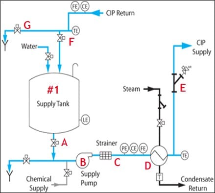
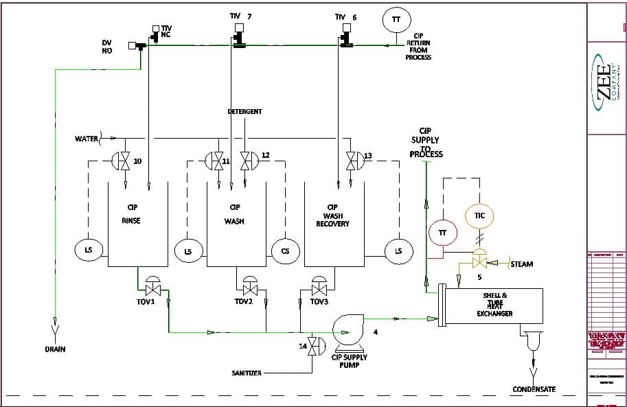
The Following the Water Principle is just that, as shown below in a single pass CIP/ACS system.
A clean-in-place checklist
Note to self, check for water!
Staying true to following the water principle, the first key item is ensuring you have water. I cannot tell you how many times over the years, the root cause of a problem has been a faulty water supply valve or level probe not allowing water to fill the tank.
- Tank outlet valve – Once you have confirmed that there is water in the tank, the next step in the path is the tank outlet valve (A). First, make sure that the valve is open.
- Centrifugal pumps – Most CIP/ACS supply pumps (B) are centrifugal pumps. The pumps will pump water forward and backward; however, the output is about 50% of the forward flow rate when running backward. It is a common mistake not to recognize this when maintenance is done, and the pump rotation is not verified after corrective actions have been completed. While this will not stop CIP flow, it will significantly impact the pump output volume.
- Inline strainer – Newer systems will have a pressure transmitter on each side of the inline strainer (C) to show the pressure differential to indicate a potential blockage. Older systems were not fitted with proper gauges or instruments for troubleshooting. So again, follow the water. Remember, if there is a blockage, there could be high pressures built up.
- Shell and tube heat exchanger – While the shell and tube heat exchanger (D) do not typically malfunction, you should never say never…I did have a collapsed tube bundle about 15 years ago that was blocking CIP flow by about 80%. Again, it was not easy to find but following the water led me to the root cause.
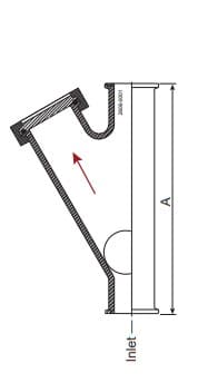
- Air blow check valve – The air blow check valve (E) could also be considered a backflow prevention device to block the supply pump from running backward between the different CIP step functions. The device shown in our drawing is called a Y check.
Check for clogs, blocks, and failed devices if there are CIP problems
CIP flow enters the check valve inlet, and then the fluid pushes the ball into the open cavity to the left, following the red arrow direction. At the same time the ball is being forced up into the cavity, it also rises above the check valve, following the (A) direction. Normally the balls used inside these check valves are rubber-coated stainless steel balls. Therefore, the balls will not fit in the (A) cavity, only in the direction of the red arrow. That is true until the rubber coating on the balls fails.
As a point of interest, I have had to use a large handheld sledgehammer and brass bar to beat one of those stainless steel balls out of a cavity (A) where it had become jammed by the high-velocity force provided by the supply pump.
Another popular version of check valves is shown below. These are disc check valves and are even more susceptible to getting blocked or locked in the open, closed, or some position in the middle.
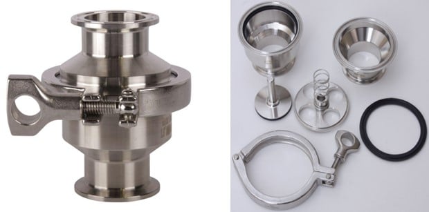
These devices typically have a higher pressure drop than the ball check valves, but they do fit in smaller footprints. Because they do not open nearly as far as other devices, it does not take nearly as much to clog them. These devices are also very sensitive to damage from hydraulic shock in the system.
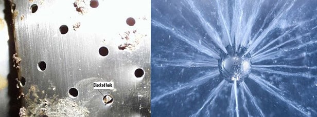
The item being cleaned or the spray devices in use could be clogged, blocked, or failed.
Many of the process systems being cleaned may also be equipped with an aseptic sampling system from QualiTru™ that detect where the water is hiding. Sometimes it is easy to find an issue, and sometimes it is not. Taking representative samples can help verify hygiene effectiveness and be effective for troubleshooting by setting up strategic sample points to compare bacterial counts throughout the CIP process.
One thing that you must always keep in mind when following the water principle is that if you are not finding it, either it did not get started on its journey, as noted in the failed level control, or there is a blockage somewhere in the process. Therefore, having your process documented is a critical first step. Not only is it important to understand how the CIP/ACS is engineered, it is also important to know what each step does.
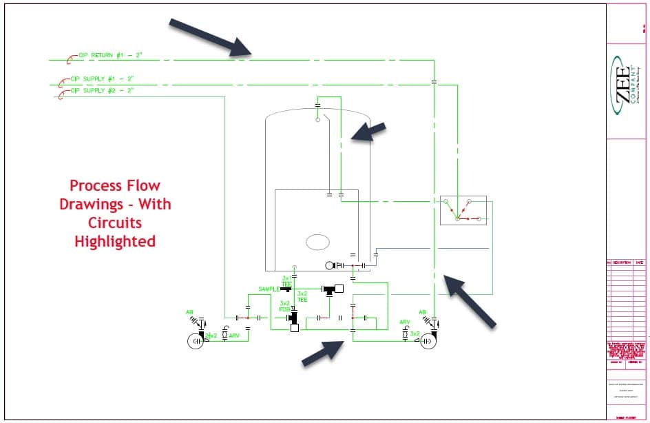
Below is a CIP rinse step drawing.
(Source: Rick Rector, Director of CIP and Dairy for the Zee Company – Division of the Vincit Group.)
In clean-in-place, the devil is always in the details
The more details or knowledge you have on the CIP and product flow in your plant, the easier it will be to follow the water. The diagram above shows an individual circuit extraction, highlighted to show the CIP path.
In these days of an ever-changing workforce, people and tools are not just nice to have; they are critical components of your quality management system.